!!!Primary Circuit
The primary (144v) needs to be fed via the protection systems (fuse, circuit breaker, disconnects) to the Controller from there on to the Motor and back to the pack.
In my current design, I have the Batteries split front and rear in cargo area of the bus for Weight distribution.
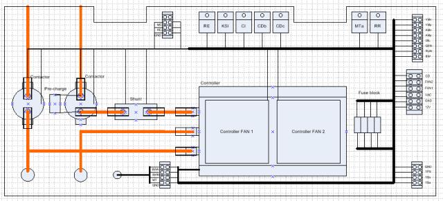
Positive going connection is made from the battery pack to the fuse and then a circuit breaker located behind the drivers seat. This travels back to the Controller panel, where it goes through the Run Contactor (RC). The RC coil input from from the secondary circuit. The circuit continues to the Shunt (1000A/50mA), this feeds the B+ input of the Controller and S1 on Motor. M- is connected via a disconnect to A1 of the Motor. The Controller needs full pack voltage for the KSI input to enable the controller, so a Bosch style relay labelled Key Switch Interlock (KSI), connects from the Shunt to the Controller input. The coil for the KSI is driven from the secondary circuit.
Negative connection from the battery pack, travels to the Controller panel, and via the Main Contactor (MC), connects to B- on the Controller.
So MC, RC and KSI must all be powered to enable current to the controller and motor to flow.
!!!Secondary circuit
!!!!Dashboard
Starting under the dashboard, the “Run” from the ignition switch is connected to the Run Latch (RL) relay as is the “Start” line from the ignition. This is connected such that when the ignition is turned from “Run” to “Start” the relay is engerised latching the 12v from the “Run” of the ignition onto the ignition “Start” line.
The “Start” line from the ignition is connected via the Interia Switch (IS) to the “Ready” lamp on the dashboard.
!!!!Dashboard to Engine bay connection
The “Ready” light side of the IS is connected to the existing “Start” wire that runs to the rear of the bus.
The “Run” cable is left as-is since it connects to reverse lights and other systems on the bus which we do not want to interfer with.
!!!!Engine bay (Controller panel)
In the rear of the bus the “Start” wire connects to the RR coil.
Aux battery voltage connects to terminal 12V on the Controller panel, this fused with a 20A master fuse, this switched via the Run Relay (RR) to the other sub systems.
The switched 12V (from the RR), feeds via secondary protection fuses other cooling systems: Motor fan, Controller bay fans and fans on actually on the Controller.
!!!!Charger interlock (behind fuel door)
A small module consisting of a old Nokia mobile phone charger (universal input voltage 100-240v) with 5.3v output, powers a small reed relay (6v coil). The relay shorts the CD line to ground when power is present at the fuel input.
!!!!Charger interlock (Controller panel / Dashboard)
CD drives relay coils ~CDb and CI, these are powered from the switched 12V so only energise if the bus is in “Ready” Mode. ~CDb (N.C.) contacts invert the signal to ~CDc so that ~CDc energised if there is no external power and therefore connect the “GEN” line to 12v, with dashboard light “GEN” is connected to the Run signal from the ignition. This means when switching from ignition “Off” to “Run” the “GEN” light has +12v one side and GND the other(since ~CDc is not energised) and the lamp is lit for “lamp test” mode. Turning the key from “Run” to “Start” latches the RR and then energises ~CDc which switches the GEN line to +12V so the GEN lamp goes out – unless of course external power is present.
!!!!Main contactor (Controller panel)
Unless CI is energised, the Main Contactor (MC) will energise when the bus is in “Ready” mode.
!!!!Run contactor & Key Switch Interlock (Controller panel)
The Throttle Pedal Switch (TPS) shorts to GND and provides a current path for RE and KSI. So only when in “Ready” mode with CI not energised can both RE and KSI be energised. The contacts for RE provide high current path to energise the RC (requires 1A to hold). The TPS is only rated at 0.16A for DC.
!!!!Motor overheat (Controller panel / Dashboard)
The thermal contacts on the Motor (MT) will normally GND to the coil of ~MTa unless the Motor exceeds 120oC. The coil of ~MTa is fed from the switched 12V so is only active when the bus is in “Ready” state. The “Oil” signal line is reused and ~MTa provides the lamp test behivour just as ~CDc does.
!!!Design notes
Considering adding brake interlock switch to interrupt run enable, when brake pedal is pushed, run contactor power is disabled. Will look into bus wiring schematics and see the best location to add this.