Controller board – now available in aluminum!
Disassembled the MDF prototype and cut and drill the aluminum mounting board and reassembled.
Controller board – now available in aluminum!
Disassembled the MDF prototype and cut and drill the aluminum mounting board and reassembled.
Tags & Insurance – the StealthBus is ready for the highways. Have a regular style tag, and an appointment booked for early Monday for the inspection to get the special AFV tag.
Many thanks to my wonderful wife Mindy for the hard work on the legal side and getting all the paperwork in order.
Fixed the passenger side turn signal and brake lights – bad lamps easy fix.
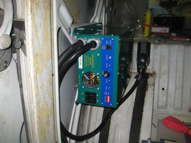
Connected the monster charger and gave the pack it’s first charge.
Cool picture of the borg like charger lit up..
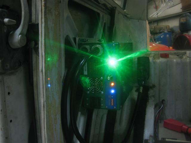
The ~PCF-30 is very easy to use and setup, I am very impressed with this charger.
Some battery math to get it set right:
|!State|!Per Battery|!Total|
|Equalization|14.4v|172.8v|
|Full charge|12.8v|153.6v|
|~50%|11.8v|141.6v|
|No charge|10.5|126v|
FIRST TEST DRIVE – WOO HOO!
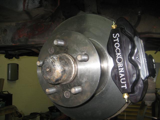
New calipers fit nicely, these 4 piston racing brakes should control the electric beastie in the back!
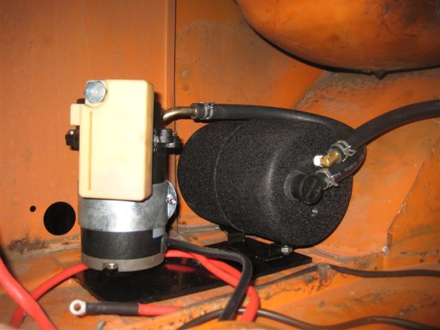
Complete basic installation of the vacuum pump, need about 6 inches more vacuum hose and to install the control relay.
Mounted throttle, connected wiring to harness.
Bus enabled with original key and motor runs under full throttle control!
New rotors fitted, temporary steel brackets fabricated with plasma cutter, figured out rear brakes mounting.
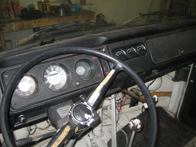
Completed wiring for PACK VOLTS, AMPS, AUX VOLTS, all gauges operate correctly. Very cool – turn the key and 160v ready to go!
Connected controller panel into bus wiring harness. Controller now enables on the stock key, and latches. One problem I found S10 (fuse) switches OFF when the key is in START position. I suspect that is bad key switch, but since it not that critical to the design I used S11, which works correctly.
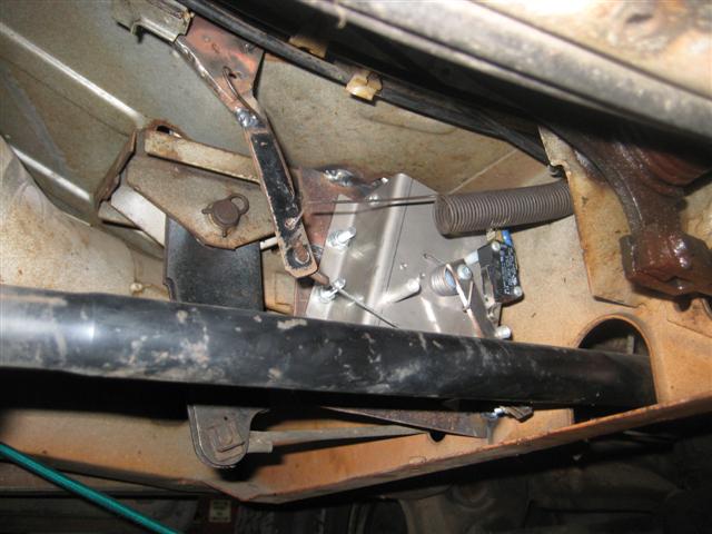
Added plate for mounted the throttle box under the throttle pedal using the worlds shortest throttle cable!
Ran 8 x 18-GA wires front to back to provide, throttle control (4 wires), ammeter and pack voltmeter connections.
Vacuum pump will be located on the spare battery tray in the back. Will fabricate a base plate to secure the pump in the correct upright position.
So the project took a 2 week break, I had hoped to have everything done in time for the big VW show in Tampa, but time ran away from us, anyway managed to get a week of and some time in the sun to recharge the human batteries!
Mounted charger, so can be easily accessed for setup / monitoring. Plan on making an armrest to house the charger.
Spoke to Manzaita orientation of the charger is not critical so I will mount on it’s side, using frame metal available.
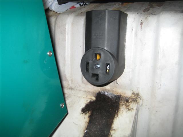
Upgraded fuel input from 20A to 30A connector, required some metal bending to still be able to mount the plug – it’s about 1cm longer than to 20A version.
Re-used some 50A cable from my old range to connect from the fuel door to a NEMA 30-14 socket inside to the bus, which the charger plugs into.
Re-used an old heater box control arm to make a linkage between the throttle cable and the pot box.
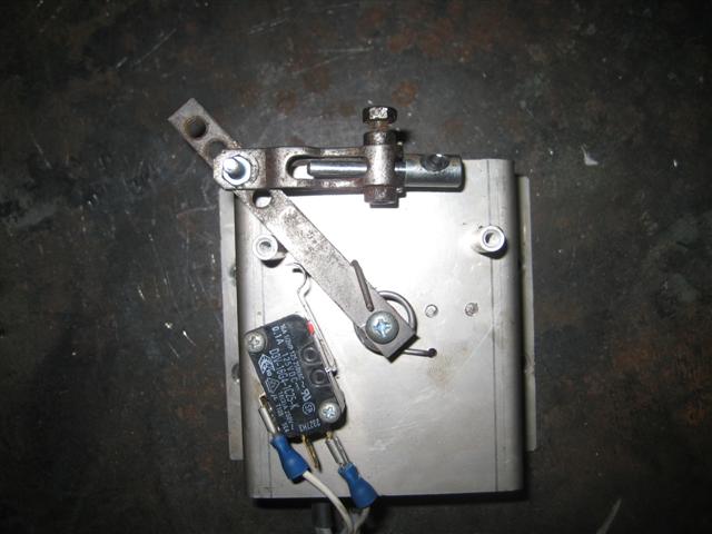
Mounted the throttle box behind battery pack, using new throttle cable. Seemed to work, but we have sticking point in cable at low position, moving the throttle guide tube changes the length of the cable, and so after several hours of adjustment and movement I have decided to abandon that design and locate the pot box under the throttle pedal, so we can control the variables much more finely and avoid some of the problems with the long cable.
Completed wiring, positioned all batteries, and fired up the complete system…. *GIGGLE* *HEHEHE*
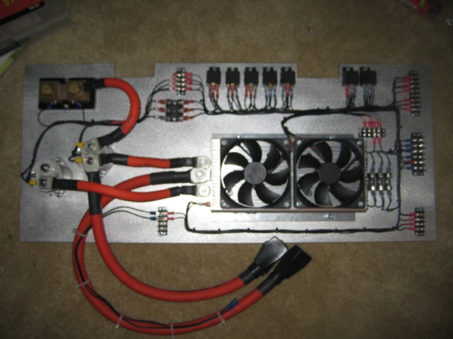
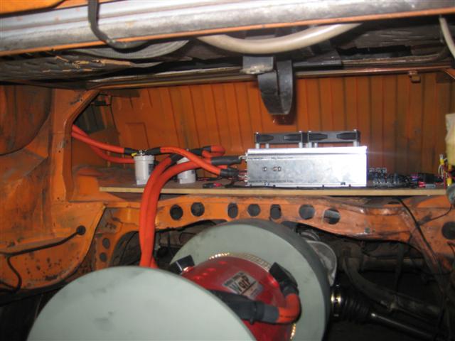
High voltage cables on controller
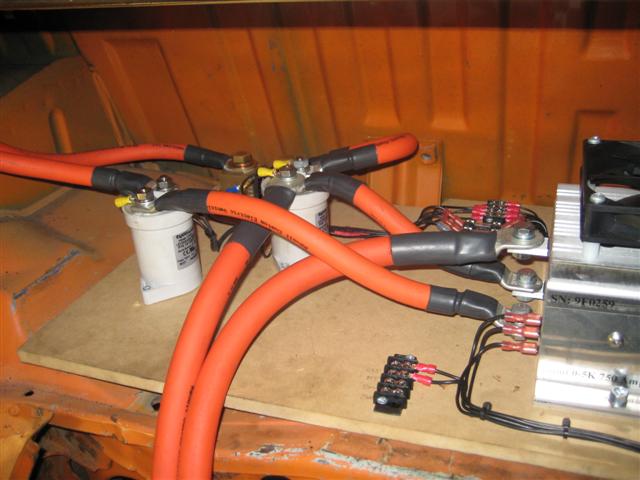
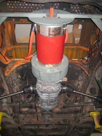
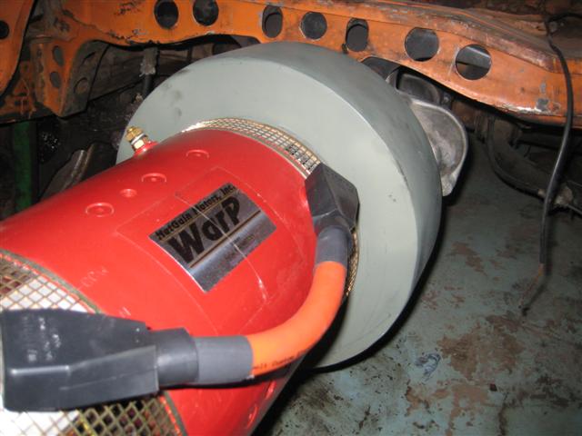
Motor and controller connected and ready to go
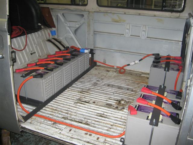
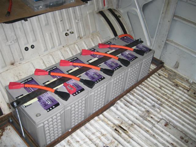
Battery wiring setup
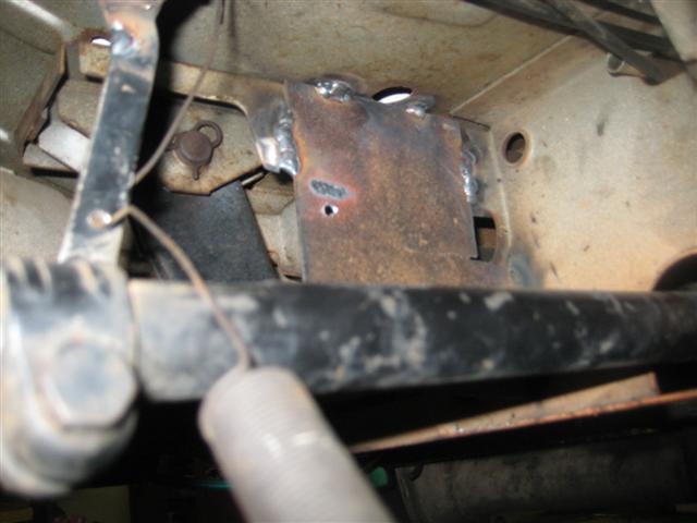
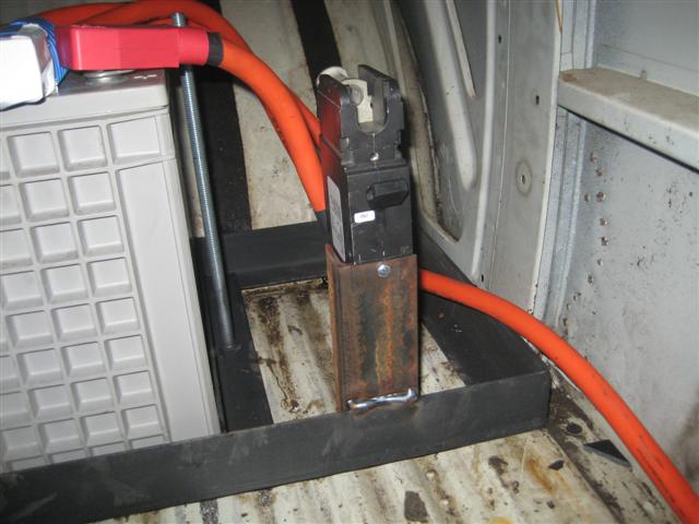
Circuit breaker bracket in position
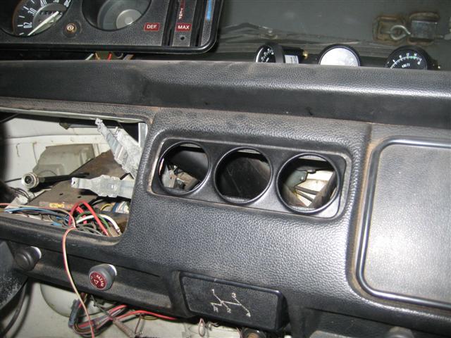
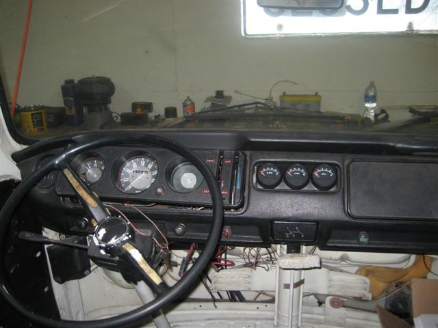
Dash mounting test of main gauges
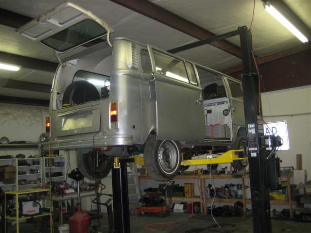
The bus getting some elevation
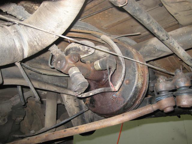
Inspection of the brake servo
Cool under bus shot of complete drive train
Front trays completed, Billie and Mike added threaded rod and bar across the top to hold the batteries down – lookin’ nice! Completed heat shrink and battery boot assembly for battery interconnects. Located fuse and master breaker, completed front battery tray interconnect cable.
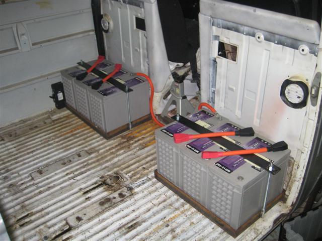
Back tray completed, ready to be bolted.
Motor mount wrapped, weld, grind, weld, grind, weld, grind, etc and primed.
Reassembled mount onto motor, shaft key inserted and fixed to coupler.
Lightened flywheel bolted on, clutch reassembled (nice German made – quality stuff…).
Transmission resealed and complete.
Attached mount to motor, transmission to mount, support bar to rear of motor and then the whole package was mounted for final assembly to the bus.
Brought heat gun and heat shrink (from Frys) to finish battery cables, heat gun lasted 3 cables and then stopped working!
Decided to reuse the radio slot for the three main meters: 80-180v (Main Pack), 0-1000A (Main Pack), 6-16v (Aux Battery). Brought a very nice trim piece from Bus Boys in CA, can get these to fit without major modification to radio slot.